Aluminium disks for closing the upper and lower hole.
These are 300mm diameter, so I can use M20 holes to mount them.
I have to wait between every M20 hole because the pillar drill is getting too hot :(


Aluminium disks for closing the upper and lower hole.
These are 300mm diameter, so I can use M20 holes to mount them.
I have to wait between every M20 hole because the pillar drill is getting too hot :(
A second hand unused water pump (normally used for heating), for only 20 euro's!
It will be used for circulating the cooling water for the turbo pump.

There isn't any room for normal M20 bolts to connect the hemispheres. To fix this I made 4 of these:

The reason for making this fusor is that I would like to try a new idea, something like the polywell, but different, something which just might be better than the polywell.
There is also a big chance that it doesn't work at all, but that's why I'm building the fusor, to test the new idea called "the Octavio".
But I'm using all my spare time to build the thing, and I have the artistic qualities snale.
So I'm looking for someone who would like to volunteer to make computer drawings to present the idea on this blog.
I planned to stabilize the HV output with a big capacitor, got 8x 4000Vdc, 8uF from surpluscenter.
They were quite big, one pin was connected to case (would become very dangerous to put them in series) and they looked rather damaged.
Surpluscenter didn't make any problem about giving the money back.
Looking at these very big capacitors it made me think of ways to stabilize my power with the 3nF/35kV capacitors.
I want to put all the high voltage stuff under the hemispheres, to make it as safe as possible.
I don't know the frequency, output impedance, induction, parasitic capacitance's etc. of my power supply, I will measure that when I have it.
For simulation I made some assumptions, two 10kHz out-of-phase sine waves of 12000V peak with both 5k impedance, two TVR30 diodes and 20pf capacitance to ground simulate the power supply. A 600k resistor simulates the load and 4x 3nF make the 12nF output capacitor.
This simple simulation gives a (completely unacceptable) ripple of 60V pp:


My HV supply is on it's way :)
Got it from High Voltage Shop
It's based on a flyback transformer with a primary resonator, it's what I wanted to build myself, but getting the parts would be more expensive than buying the whole thing.
The output it not stabilized, I got some 4000Vdc, 8uF capacitors from surpluscenter.com, but they are quite bulky and look a bit damaged, I don't think they are save.
I have the 3nF/35kV capacitors (see previous post), I don't know the frequency the supply works with, but that would probably be somewhere between 10 and 20 kHz.
I will publish a working stabilized HV power supply soon!
Also got a second hand transformer/cascade which I might use for PMT supply etc:

Not that much time (again!), just enough time to mount one hemisphere and the heat rediator (for turbo pump cooling water, important during bakeout):


For my experiment I need 8 hot cathodes with grids in front of them to control the current.
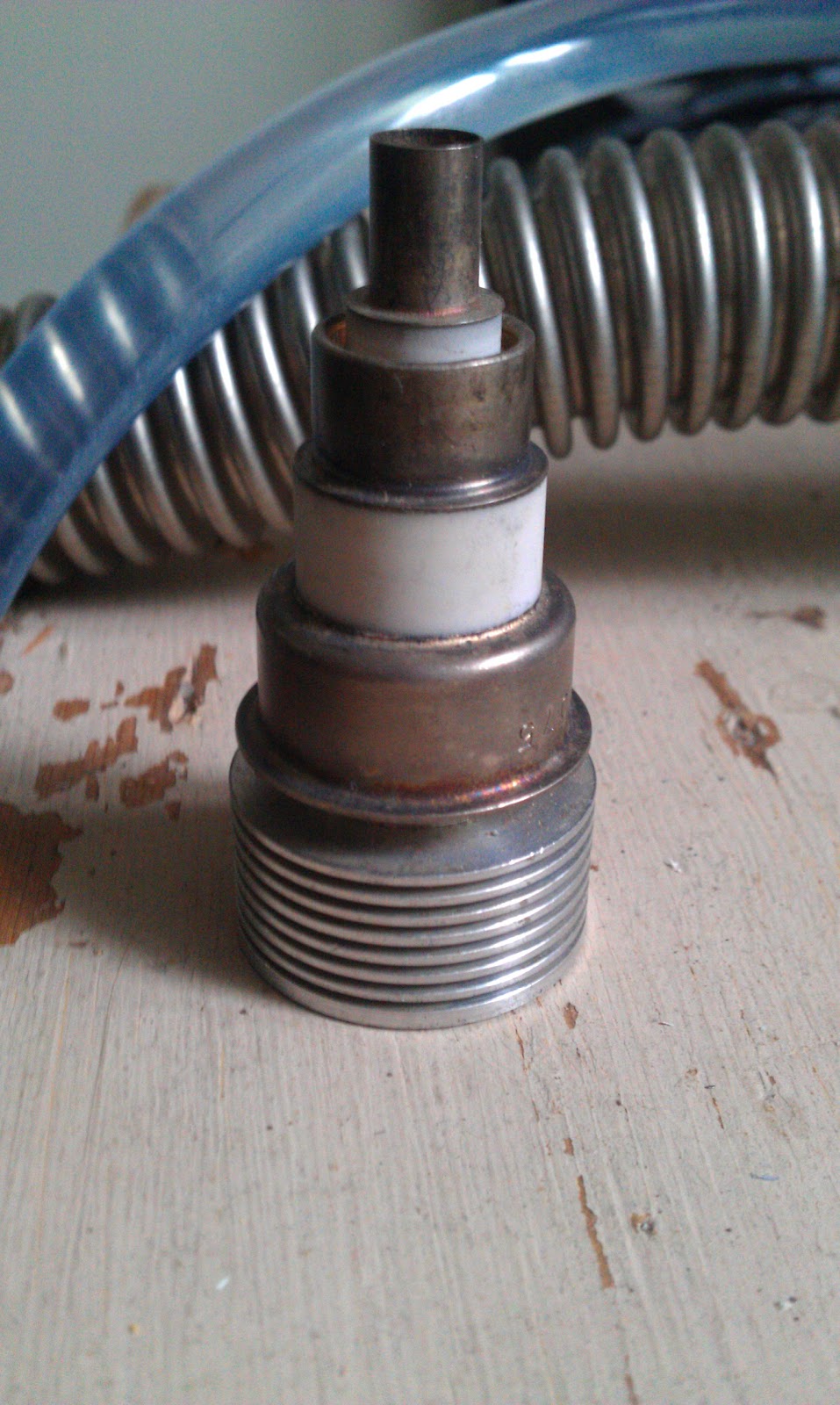
Got 10 2C39 tubes on marktplaats.nl, the idea was to cut them open and use the filament, cathode and grid as a controllable source of electrons.
But... I found that the white ceramic material could contain beryllium oxide! Not a good idea to cut it, small beryllium oxide particles can be very toxic.
Maybe it is possible to cut the metal (the grid connection), I don't know if there is any ceramic material under the grid connection.
Before I mount the turbo pump in the rack, I did a test run with water cooling for 4 hours. Got 2.2E-6 mbar, steady pressure. First run gave a pressure of 1E-5 but kept "jumping" to 5E-4 mbar, after cleaning the ring on the fore-vacuum side the pressure stopped "jumping".

Not that much time last weekend, the sheep had to be shaved, but I did had time to weld the last bar in the rack, galvanize it and make some holes for the hemispheres in the aluminium ground plate. It killed my drill.
Here are the pictures:


Dit some more work on the rack last weekend, the Pfeiffer & Balzers controller en pressure display fit exactly between the upper steel bars.
The hemispheres and turbo pump will be mounted on the aluminum ground plate.
Here is the picture:
